Microgrid Optimization
Create an ad hoc microgrid with a variety of resources that reacts dynamically to the addition of load and generation resources

Introduction
With the power grid becoming even more dynamic, there is a need for not only microgrids, but microgrids that can adapt to a changing topology. With the addition of Electric Vehicles (EV) and the need to adapt to failures due to fire and weather, the layout of a microgrid, and the availability of resources, may change relatively quickly.
This creates many operational challenges that need to be addressed in the design of communication, control, and protection systems. Different grid scales also require different solutions, with transmission networks having significantly different requirements than substation-level microgrids. Architecting the multiple layers so that they work together without conflict is essential. The grid infrastructure needs efficient, advanced communications, control and metering infrastructure at all levels. At the edge, microgrids need to not only be able to operate independently for at least short periods of time, but also need to provide services to the larger networks including power generation, power quality control, voltage and frequency support, and load balancing. As resources at the edge change over time, being able to plug-and-play Distributed Energy Resources (DERs) and properly share the current state among them is critical. This is where RTI Connext has a critical role. This Case + Code provides a framework and reference architecture for grid edge interoperability and distributed intelligence. The framework consists of business-driven, top-down business case, use case, data modeling and implementation approaches.
The following diagram illustrates communication within and between the different components.

The grid of the future will require treating data differently; leveraging metadata and performing analysis locally to process the mountain of new data available from new technologies. Traditional headend systems have relied on relatively few sources of field information. New asset classes on the grid (AMI, smart inverters, PMUs, etc.) have added large amounts of data that can quickly and accurately describe the state of the power system. Traditional headend systems were not designed to process this increased volume of information as quickly as is needed to react to current operational scenarios and fully realize the benefits of these new grid edge assets.
Information no longer needs to go to the central system to enable decision making. Federated local data can be made securely available between assets at the grid edge to complement and enhance operations. As resources come online and go offline, this data can be used to maintain microgrid viability and even network groups of microgrids together when disconnected from the main grid.
-
What This Example Does
This Microgrid demonstration utilizes simulators instead of actual devices and single technology choices rather than multiple to illustrate operational interactions between field devices and microgrid services. The simulator demo consists of the following simulators and processes.
- Solar Simulator (PV)
- ESS simulator (ES)
- Generator Simulator (Generator)
- Load Simulator (Load)
- Recloser Simulator (Main)
- Power Flow Simulator (PowerFlowSim)
- Optimization (Optimizer)
- The Visualization of the System (HMI)
The demonstration shows the communication capabilities between peer resources and simple power flow optimization. Two scenarios are detailed below.Scenario 1: Islanding
The first scenario shows the basic microgrid functionality of islanding the microgrid in the case of the recloser connecting the microgrid to the main grid tripping open.
- Start with Maintain mode – only when grid connected
- User trips recloser
- Islanded – fake mode to set voltage source sent by recloser when tripped
- The Island balancer app sends setpoint to the battery to balance the system
- User closes recloser
- Leaving Islanding – sent by recloser when recloser closes
- Then app sets Maintain mode sent by the recloser
Scenario 2: Additional ResourceThe second scenario shows how the microgrid adapts to the addition of an another set of resources.
- Start with Island mode (grid disconnected)
- Additional unit containing a load, energy storage unit, and PV is added to the bus
- System rebalances resources to utilize and handle new liabilities and resources
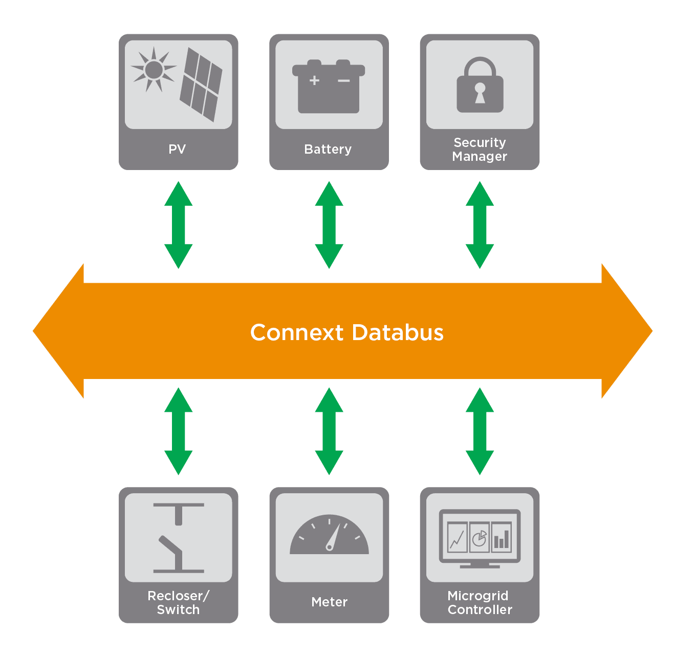
System DescriptionThe different applications are connected through the RTI Connext Databus as shown in the following figure. In other words, each application uses Connext to share data through a logical databus.
In this example we are using a simplified data model designed to limit the data on the bus to only that which is needed for the use cases we are demonstrating. All data is keyed to the device it originates from (with one exception). More information on the data model can be found here.
Solar Simulator (Solar PV)
The solar simulator publishes the PV system power (PV output), PV system information, and PV system status. The solar simulator subscribes to control topics for connection and output (curtailment). There is also a subscription to a solar irradiance topic used for simulation.
ESS Simulator (EnergyStorage)
The ESS (Energy Storage System) Simulator publishes the power it is absorbing or generating, status, system information and VF Device capability. The status includes the system's SOC (State of Charge) and whether or not the system is acting as a VF Device. The ESS Simulator, along with the Generator Simulator can act as a VF device in island mode and includes code that simulates this behavior. The ESS simulator subscribes to control topics for connection and output. There is also a subscription to a topic used to manually establish SOC for simulation.
Generator Simulator (Generator)
The Generator Simulator publishes the power it is generating, status, system information and VF Device capability. The status includes whether or not the system is acting as a VF Device. The Generator Simulator, along with the ESS Simulator can act as a VF device in island mode and includes code that simulates this behavior. In the case of the generator simulator, a delay is included that does not allow the device to output power if it is disabled.
Load Simulator (Load)
The Load Simulator publishes the power it is absorbing, status and system information. The simulator subscribes to a Control message that allows the Load to be connected or disconnected from the grid independently. There is also a subscription to a topic used to manually set load for simulation.
Recloser Simulator (MainInerconnect)
The Recloser Simulator publishes the power flow through the main interconnection between the microgrid and the main grid. This is the device that is responsible for islanding and resyncing the microgrid from and to the main grid, as well as managing the active VF Device. The Recloser Simulator publishes the power flowing through it, along with device status, device information and microgrid status. The simulator subscribes to a topic that allows for planned islanding, planned resynchronization and immediate islanding.
Power Flow Simulator (PowerFlowSim)
The Power Flow Simulator takes information from each device on the network and generates the powerflow through the main interconnection. The simulator subscribes to all measurement topics and publishes to a topic used by the main interconnection for its power measurement topic.
Controller (Controller)
The Controller handles setpoints for devices during islanded mode, along with decisions regarding the active VF Device. It publishes to device control topics and VF Control. The simulator also subscribes to all measurement topics in order to help balance the system during islanded operation. The optimizer also sets up VF Control transfer between the simulated ES and Generator systems.
Visualizer (Visualizer)
The Visualizer allows visibility to all elements of the system, as well as control for solar irradiance, state of charge and manual device control. It publishes to the solar irradiance, state of charge and device control topics. It subscribes to all measurement, status, and information topics for presentation. The visualization uses GTK for generating the GUI, making it relatively cross-platform.
-
Running the Example
Download the Example
The example has been configured and tested on Windows 10 64-bit and Ubuntu 16.04 64-bit. The example can be downloaded from the RTI Community GitHub repository. To run the example, you need Google Chrome installed on your system.
Build the Example
You must build the example in order to run the simulators. Full instructions for building the example can be found in the RTI Community GitHub repository.
Run the Example
To start the demo, go to the scripts directory and run runAll.sh.
The script will start all devices, as well as the Visualization.
-
QoS Considerations
The QoS file for the examples is in the root project directory. Measurement topics use Best Effort and Control topics use Keep Last Reliable, while Info and Status topics utilize Transient Local Reliable communication. Additionally, Ownership and Liveliness QoS is used throughout the system for device control and determination of which device to utilize as the VF Device.
There are several considerations when choosing QoS for a system.
- Measurement is used for optimization, control and simulation, which makes it very important. But, it is also a continuous stream of data that should not (especially in the real world) change much over a period of 100 ms. Due to the rapid update rate, and no requirement for history, the potential for lost packets is outweighed by the performance gain to the system. If measurement data were being updated at a slower pace, reliable communication could be warranted.
- Info and Status information changes seldom and asynchronously. In fact, the data in the Info structure should be static (outside of reduction of functionality due to aging, damage or maintenance). Due to these facts, and to preserve this information for late joiners, the topics need to be not only reliable, but use Transient Local durability to allow this information to be available to all system elements, current and future.
- The Control topics require considerations beyond the others in this application. With the potential for loss of a controlling device and the potential for devices responding to late information, limiting the lifespan of data and placing a deadline on the reading of samples is needed, in addition to reliable communication.
As far as the use case where individual devices receive and process sequences of commands across the databus, in this implementation, this would neither be supported nor allowed. Sequences of control should be handled at the device level, with parameters defining variation of such sequences being provided to the device. Timing and proper sequencing would then be handled in the device code itself. - The last topic for consideration is the exception among the topics used in this system. The VF topic allows for multiple devices to vie for VF control of an islanded microgrid. This topic is unkeyed and uses ownership strength to determine the winning instance. In this example some simple math is used to give preference to the Energy Storage system when it is fully charged and to the Generator when the Energy Storage system is near empty. This allows all devices with this capability to broadcast it, and the Controller to watch for instance changes and react accordingly.
-
Next Steps
Join the Community and post questions on the RTI Community Forum.
Contribute to our Case + Code examples on RTI Community GitHub using these instructions.
 Success-Plan Services